Exploiting the properties of thermal radiation is a smart approach for your inspection process.
Integrating infrared cameras and radiometry into the production process allows you to see and measure temperature differences and absolute temperatures.
Thermal radiation is infrared “light” - so you can do without extra lighting or make hidden structures visible through specific stimulation.
The thermography app for vicosys brings industrial thermography to a new level.


Monitoring temperature-critical processes and fire protection
Monitoring temperature gradients with vicosys® also offers outstanding customer value, particularly in very small areas where processes are at risk of overheating or fire. Another outstanding field of application is the temperature monitoring of automated processes.


Industrial interfaces
All vicosys® systems have industrial communication interfaces. They fulfil the highest standards of integration and flexibility.
- EtherCAT and PROFINET for real-time communication and end-to-end processes
- modbusTCP and TELNET for communication via Ethernet networks
- digital I/Os for maximum compatibility with older systems and stand-alone applications


vicosys® - machine vision system
Image processing systems of the vicosys® series are the evaluation system for the thermal imaging cameras. With an activated thermography licence, you can connect up to 16 thermal imaging cameras to one system.
Recommended products:
- vicosys® 5300
- vicosys® 5400
- vicosys® 6300
- vicosys® 6100
- vicosys® 19001
Thermal imaging cameras from TELEDYNE FLIR
It supports the A15, A35, A65 and the new A50, A70 series in the standard image streaming configuration via POE.
The supported thermal imaging cameras have the following features:
- Microbolometer technology
- available resolutions: 640x512 (A65, A70), 320x256 (A35), 80x60 (A15), 464x348 (A50)
- Integrated optics with 29°, 51° or 95° angle of view
Depending on the camera model and measuring range, temperatures from -50°C to 1000°C can be detected.


Current vicosys® successor models and thermal imaging cameras
Image processing systems of the vicosys® series are the evaluation system for the thermal imaging cameras.
With an activated thermography licence, you can connect up to 16 thermal imaging cameras to one system.
From firmware version v300, the vicosys® 6300 supports the new TELEDYNE FLIR A50 and A70 thermographic cameras.
The vicosys® 6300 machine vision platform is the successor model of the vicosys® 5300, the two thermal imaging cameras follow A35 and A65.
Thermal imaging is used to visualize thermal radiation. This is a simple and direct method in processes where heat plays a role.
Although a large proportion of the development of thermal imaging originates from the military sector, where the technology can be used extremely well to identify people, vehicles and aircraft, industrial processes where temperature effects are important are no less widespread.
Areas in which temperatures play an important role in processes include:
- Plastic injection molding
- Pressure die-casting
- Soldering
- Welding
- Sealing of sealed pouches
- Sealing of food packaging
- Hot forming
- Laser cutting
- Processes with active cooling
- Heat preserving
- Melting of plastics
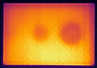
The main advantage is that, with surface materials that are unvarying and uniform, the temperature can be determined directly based on the thermal radiation. A difference of just 5 K is enough to generate a thermal image with sufficient contrast.
Active lighting is not necessary. Since one of the main challenges in conventional image processing is to determine the correct lighting, the use of thermal imaging in temperature-related scenes represents a significantly simplified solution.

In the car more and more large parts made of plastic are included: center consoles, bumpers, dashboards but also various trim elements, as well as their hidden support.
Defective locking lugs, over-molding and missing material can have expensive consequences for the automotive supplier if discovered later.
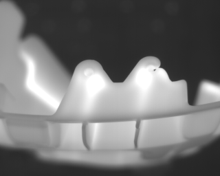
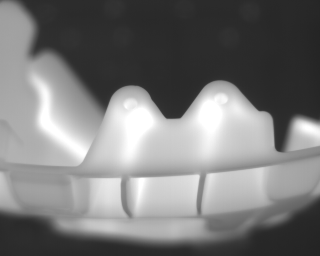
An innovative approach is to inspect large components immediately after spraying. At this point, a robot removes the part from the mold and holds it in front of a thermal imaging camera before it is deposited on a conveyor belt. To make the details visible, different detail positions are approached one after the other. Thus, the last filling point, locking lugs, the injection point and function-relevant details can be 100% controlled.
Since the part itself is still warm, thermal imaging cameras can easily generate a meaningful image for all component types. This is a great device advantage because the lighting design for different components is very prone to error and costly.
In addition, locking lugs, which are positioned in front of a material, can not be tested reliably with classic lighting. By considering the heat distribution of the component, however, this is easily possible with thermal imaging cameras, because locking lugs cool down considerably faster compared to solid material and thus create a contrast to the background.
Thanks to the simple concept with webHMI, the end customer can quickly look for new components themselves.
In cooperation with industrial thermography Schweiger, a solution has been developed that is faster and more reliable than any other known system on the market.
The system was standardized and advertised under the name "ThermoInspection".
Sector: | Automotive (Plastic Inspection Moulding) |
Used Components: |
|
Customer/System partner: | Magna HIG / Industriethermographie Schweiger |
Yes, the vicosys® thermography option is already being used successfully to inspect sealing seams on packaging in the medtech and pharma industries.
Specifically for these applications, thermography is a fairly simple and direct method of quality inspection.
The key value is that the sealing process applies heat into the materials, which can be measured directly using radiometry.
Even relatively low gradients of only 5 K will deliver reliable contrasts as a fundament for the inspection process.
Please do not hesitate to contact us to discuss your individual thermography solution.
For most image processing experts, the use of thermal imaging is still very new. Vision & Control has launched a new cooperation with Flir, a well-established thermal imaging camera manufacturer, as an easy entry point to the world of thermal imaging. After an intensive collaboration between our two companies, we can now offer plug & play connectivity between the relevant industrial camera series Flir Ax5 and our vision system vicosys®.
Here, the camera can be corrected using a standard Ethernet cable and images can be directly captured and processed via the usual pre-defined image acquisition commands in the parameterization software vcwin.
There are a few special commands for temperature measurement, selection of the displayed temperature range, and for controlling the self-calibration process (NUC).
The emissivity describes the degree to which radiation is transmitted at the boundary of the surface. The portion that is not transmitted is reflected back into the warm body. A value of 100 % means that all radiation is transmitted through the interface. This means that with thermal imaging cameras, the temperature of materials with an emissivity of 100 % can be measured directly by converting the received radiation.
Interestingly, the emissivity applies to both directions. Materials with an emissivity close to 0 % are mirrors. The statement about the temperature can only be made if the environment is extremely constant. Fortunately, the plastic materials on printed circuit boards have a fairly high emissivity. This makes this test of chip temperatures a fairly uncomplicated matter.
In order to determine the real temperature, a part of a test object can be set to approximately 100% once by using suitable black matte paint. In this artificial scene, reflections play no role and the temperature can be determined directly. The emissivity can be adjusted so that the temperature measured in the unpainted area corresponds to the temperature in the painted area.
Tactile temperature sensors offer an alternative for this process.
Since the cameras themselves get warm, the readings of the heat-sensitive pixels would get out of hand after the camera is switched on. To bring them back to the known temperature, a small plate can be pushed in front of the sensor and all pixels can be calibrated to the temperature of a sensor on the plate. This step does not take long, but should be triggered occasionally every 20 to 30 minutes in the test programme. Since the timing should not be done exactly during a measurement, this can be placed by the test programme editor vcwin at a location to be determined by the user. Two points are typical: At the start of the system and occasionally after a measurement.
Unlike visual cameras, thermal imaging cameras do not have an exposure time. They always work with a fixed recording time. However, the recorded temperature range is quite large, ranging from -50 °C to 600 °C. In order to obtain a high-contrast image, the range used must be reasonably narrowed down. This range (e.g. 30 - 80 °C) is the set spread.
Since typical optical materials such as glass do not transmit thermal radiation, lenses made of a special material are necessary.
For this type of camera, lenses made of germanium semiconductors have become widely accepted. Inexpensive systems use lenses made of an infrared-transparent plastic body with a germanium coating.
In the FLIR Ax5 series, the complex germanium optics are already integrated into the camera. There is a choice of different image angles for the appropriate working distance.
The field of view results from the angle of view.
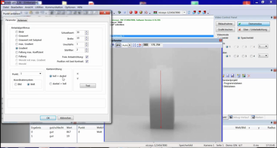
With the well-established vcwin software, which is used to create test sequences, you can easily use the image acquisition command to capture an image and then use additional commands to check the temperature in an inspection area. Of course, all the familiar image processing commands can also be used (Compare pattern, Measure distances, …). However, when using a thermal imaging camera there are also a number of special commands that need to be considered in addition to those for a standard optical camera:
NUC, Spread and Emissivity.
The basis of our components for thermography is the vicosys® 5300 or vicosys® 5400 with FLIR Ax5. It is important to consider the thermography licence to enable the additional commands (NUC).
In principle, these components can be sampled. Contact our sales department, they can recommend the necessary components. There are beginners' videos on this subject.