


vicotar® telezentric lenses
- Have diffraction limited imaging quality
- Are with adjustable aperture
- Image many object field sizes from a few micrometres to several centimetres
- are available for all common sensor formats (1/3" to 1.2", DX format, 35 mm format)
- are available in different lens series
Blue Vision (compact), bi-telecentric (both sides), standard, large field, microscope lenses.
- A wide range of suitable illuminators is available
- Depending on the application, telecentric illuminators, single-mirror illuminators, area illuminators or ring illuminators are suitable
- Have a wide range of accessories and many combination products: UV blocking filters; colour filters lens holders, deflection mirrors; beam splitter unit, vision systems
- Development of customised lenses possible


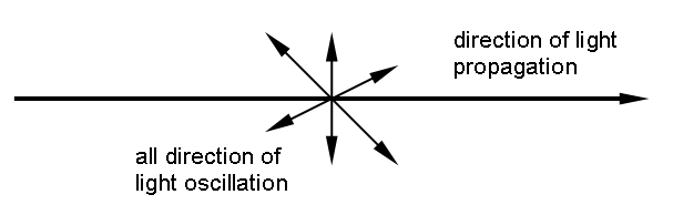

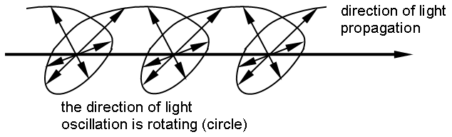
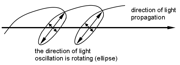
Polarization occurs on smooth surfaces (reflection) or during transmission through optically active materials (polarization filters) and occurs in various forms: Linear, circular, elliptically polarized light.
Entozentric

The natural perspective with which the human eye sees is the entocentric perspective. The perspective centre Ze lies in front of the object from the direction of observation. Here, objects appear larger the closer they are to the observer. Based on experience of the actual size of an object, the distance of the object can thus be estimated. In the case of depth-extended objects, the natural perspective impression results in the foreground contours of the objects obscuring the deeper ones.
Entocentric lenses realise the entocentric perspective.
Most photographic lenses and also most lenses in image processing are entocentric. Very small sizes possible, various qualities. With oblique top view, perspective errors occur.
For observation tasks, presence control, attributive inspection (part large/small, high/low), colour control. - The possibilities for measuring are severely limited (exceptions: flat, level parts, but only at constant s. working distance).
Telezentric

The centre of perspective lies at infinity in the direction of observation. The result: objects of the same size appear to be the same size both at long distances and at short distances. This impression of perspective can be created in the eye by an upstream optical instrument, such as a microscope, by mapping the pupil of the eye to infinity on the object side. Since all rays of vision now run parallel, the size of the objects is independent of the distance to the observer. This also means that it is no longer possible to make a statement about the distance of an object.
Telecentric lenses realise the telecentric perspective.
For inspecting and measuring on any spatial parts with holes, grooves or apertures at different heights - together with telecentric illumination, precision measurements are possible.
Hypercentric

The centre of perspective lies behind the object in the direction of observation. This makes an object appear larger the further away it is from the observer, i.e. exactly the opposite of the entocentric perspective. In order to convey this impression of size to the eye, an optical instrument is again required, for example a simple magnifying glass, which images the pupil of the eye in front of the object. This makes it possible, for example, to look at the lateral surface of a cylinder viewed from the front.
Hypercentric lenses realise the hypercentric perspective.
Special lens in industrial image processing for inspecting lateral surfaces.
Telecentric wide field lenses are a special form of telecentric lenses. Above a certain diameter of the front lenses of approximately 200 mm, the costs, weight and also the mounting effort of classical glass lenses increase considerably, so that industrial suitability can no longer be guaranteed. In order to capture large objects nevertheless, the front lens group is designed as a Fresnel lens. The entire lens can thus be realised in a lightweight design. This opens up new possibilities for the industrial use of telecentric lenses. Despite the use of the Fresnel lens, a good modulation transmission results when using a megapixel camera right into the image corners. A correction of the principle-related colour errors is not possible. Therefore, large field lenses should always be used together with monochromatic illumination. Telecentric large field lenses are possible up to a diameter of approx. 800 mm.
Telecentric large field lenses are used, among other things, for the inspection of car catalytic converters, heat exchangers, champagne bottles and for handling tasks in the semiconductor industry.
For a simplified lens selection, a lot of relevant information is already included in the lens name. The following guide is intended to make lens selection easier for you.
Step 1: The lens.
The maximum lens dimension determines the diameter of the lens. This is the first key figure in the lens name. In addition, the realisable object field dimensions are given for each lens in relation to the sensor format.
Step 2: Camera and sensor
Which lens mount does the camera have? How large is the sensor?
The second lens code shows the maximum sensor diagonal that the lens can serve. By default, our lenses have a C-mount connection. But lenses are also available for the M42 mount.
Step 3: The working distance
The third figure in the lens name is the working distance. Together with the lens length, it determines the required installation space. Here it must be checked whether the lens fits the mechanical boundary conditions of the place of use. Our deflecting mirrors and our extensive range of accessories allow maximum flexibility here.
Step 4: Optical quality parameters
The manual provides extensive information on the quality of the lens, such as depth of field and resolving power. In this way, the optimal aperture can also be determined. The pixel size of the sensor should also be taken into account. This limits the maximum resolvable spatial frequency via the Nyquist criterion. The sensor size, in turn, actually has an influence on the depth of field. After these considerations, it may well be necessary to change to another camera model with a different sensor size or a different pixel size.
You can get more information here or ask our team of experts for advice in this regard.
Examples:


