Tipp 1

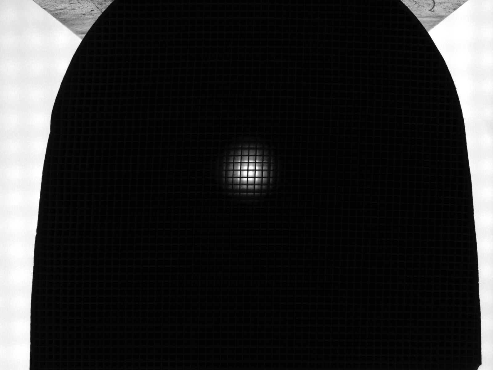
Often, the sharpest lens adjustment can be achieved by setting it up for the center of the depth of field. To do this, proceed as follows:
- Fully open the aperture at the lens (this produces an image with the smallest depth of field).
- Make sure that the image is not overexposed (adjust the exposure time and/or brightness as required).
- Get the image into sharp focus; to do this, use e.g. the tools in the BV software (‘Focus’ function) – if necessary, fix the distance setting.
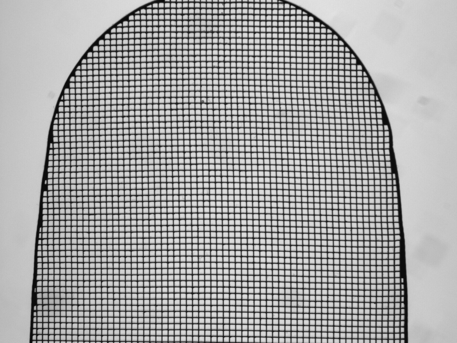
- Reduce the aperture down to the required settings – fix the aperture setting.
- Adjust the exposure time and/or brightness so that the images are not overexposed.
This approach will ensure that there is an approximately equal depth of field to the front and to the camera.
Nomenclature:
type - covering resp. beam shaping - light-emitting surface - wavelength - special features - control mode
Type: A (area), L (bar/line), R (ring), D (dome), DF (dark field), S (spot)
Cover: CLR (clear), DIF (diffuse), POL (pole filter), LEN (lenticular)
Special features: P (Power-LED), V (stainless steel)
Control mode: SL (smart light technology, no internal controller), UDC (no internal controller), 24V (24 V with LED controller for static or switchable operation)
Example 1: L-CLR-10x300-R633-P-SL
· Bar light
· Clear cover
· Light-emitting surface: 10 mm x 300 mm
· Wavelength: red 633 nm
· Power-LED
· SL - smart light technology, without LED controller, flashable, all lighting parameters can be set with an LED controller (e.g. DLC3005)
Nomenclature (historical):
type and light-emitting surface – wavelength resp. light colour / control mode / special features
Example 2: LAL7x25-R633/24V/IP67
· reflected bar light (directed) with 7 mm x 25 mm light-emitting surface
· Wavelength: red 633 nm
· 24 V with LED controller for static or switchable operation
· Degree of protection: IP 67
Example 3: LDL14x50-W5K7/UDC/-a
· Bar light back light (diffuse) with 14 mm x 50 mm light-emitting surface
· Wavelength: white 5700K
· UDC: without LED controller, flashable, all lighting parameters can be set with an LED controller (e.g. DLC3005)
· -a revisions
Nomenclature:
Max. diagonal length of object /
max. diagonal length of image -
Working distance -
Aperture (variable, fixed) -
Optimized for light spectrum (B, WN, NIR, ...) -
Optional: "Vibration-proof" (RF)
Example: TO18/6.1-95-V-B
- Telecentric lens
- Maximum object size 18 mm
- Max. diagonal length of image 6.1 mm (1/3” sensor)
- Working distance 95 mm
- Aperture: Variably adjustable (V)
- Optimized for applications with blue light (B)
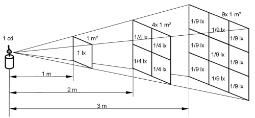
According to the photometric law of distance, the incident light reaching the test object decreases proportionally to the square of the distance. The further the lighting source is from the test object, the weaker the illuminance (irradiance) at the test object.
Brightness, assessed for the human eye:
Illuminance Ev
Unit: [lx] ("LUX")
The illuminance describes the light reaching a surface that is visible to the human eye.
Brightness, assessment of energy:
Irradiance E
Unit: [W/m²]
The irradiance describes the electromagnetic energy arriving at a surface (i.e. the test object).
Statement of the brightness of vicolux incident light illumination systems:
Vision & Control always uses the energy quantities to state the brightness specifications of incident light illumination systems.
For incident light illumination systems the irradiance is stated in [W/m²] – usually for a working distance of the lighting of 100 or 200 mm.
Image scale ß`
This describes the ratio between image size and object size and has a positive or negative sign. It indicates the magnification or reduction of the image.
Definition: |ß´| = |y´/ y|
y´ - image size
y - object size
ß´ > 0 non-inverted, non-reversed image
ß´ < 0 inverted image (top-to-bottom)
The image scale is often stated without a sign, and the letter "m" (for magnification) can be written for this instead.
m = ß´
The following applies:
m < 1 reduction; a large object is reduced to the sensor size (typical case: landscape image)
m = 1 object size and receiver size are identical
m >1 magnification, a small object is enlarged to the receiver size (typical case: microscopic images)
Example 1:
Object size y = 1 mm, image size y´ = -10 mm
ß´ = -10 (:1), m = 10
--> 10-fold magnification
Example 2:
Object size y = 60 mm, image size y´ = -3 mm
ß´ = -3 / 60 = -1 : 20 = -0.05
--> 20-fold reduction = m = 1/20
Task definition:
It is often necessary to protect Machine Vision systems against ambient light – direct sunlight, hall lighting – in order to improve the reliability of the systems and make them more robust.
Standard procedure:
Mechanical enclosure of the image processing structure in order to suppress external light influences.
Disadvantage: Mechanical solutions such as enclosures or the attachment of light protection screens are expensive and not always possible.
Efficient solution:
Sufficient protection against ambient light can already be achieved by using vicolux® BLUE Vision LED lighting in combination with a blue colored glass filter (available as an accessory for the lens).