
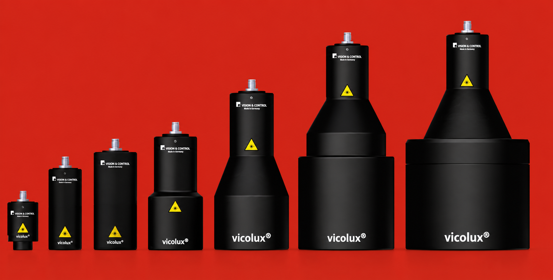
Telecentric illumination provides a crucial basis for robust measurement processes. Its nearly parallel beam path produces an exceptionally homogeneous backlight and enables extremely high-contrast edge imaging. This not only improves edge detection but also reduces measurement errors caused by stray light, reflections or perspective effects. Telecentric systems are particularly indispensable when inspecting transparent, glossy or highly reflective test objects – such as glass ampoules, precision wires, metal pins or semiconductor structures.
Vision & Control is one of the technological pioneers that introduced telecentric lenses and illumination systems to industrial image processing at an early stage and consistently developed them into integrated measurement systems. The combination of vicotar® lenses and vicolux® illumination systems has resulted in solutions that now set standards in numerous measurement and inspection applications. Development and production take place entirely in Germany – a decisive advantage when the highest levels of precision, reproducible quality and many years of application experience are required.
The key advantage of telecentric illumination lies in the so-called shadow projection principle: edges and contours are rendered with maximum contrast as a silhouette image. This makes it possible to reliably detect even the smallest dimensional deviations – a fundamental requirement for highly precise inline measurements in automated production processes.
Design and operating principle
Telecentric illumination systems from the vicolux® series generate a highly parallel, i.e. collimated, beam path. They have been specifically developed for industrial image processing and optical metrology in order to minimise diffuse reflections and highlight edges with maximum precision. Telecentric illumination can only be used in conjunction with telecentric lenses, as only these can process the parallel beam path correctly from an optical perspective.
In its basic form, a telecentric illumination system consists of a point light source positioned at the focal point of a lens. Since light rays emerging from the focal point leave the lens in parallel, the desired parallel beam is produced. In combination with a telecentric lens, this enables a test object to be captured using highly precise backlighting. The resulting image appears as a high-contrast silhouette against a uniformly illuminated background.
Figure 1 shows such an arrangement.

Figure 1: Telecentric measurement setup
Image source: Vision & Control
The light source (LED) is located in a uniformly illuminated aperture stop of defined size. This gives the beam path a precisely defined aperture, which is required for accurate imaging. An image of the light source is reproduced in the aperture stop of the lens. The test object is imaged onto the camera planes and appears as a silhouette against a uniformly illuminated background.
It now becomes clear that the apertures of the illumination system and the lens must be matched to one another. The aperture of the lens should be adjusted so that the image of the light source completely fills it. Opening the aperture further does not make the image brighter, as the aperture of the illumination system determines the beam path. It should be adjusted so that, when the aperture is closed, the image just remains fully illuminated. This ensures that the apertures are matched and prevents interference from possible ambient light.
The size of the light source and the focal length influence the divergence angle of the rays.

Figure 2: Light source divergence as a function of focal length: the illuminated field diameters are kept constant for this example.
Image source: Vision & Control
The tangent of the divergence angle is calculated from the ratio of half the illuminated field diameter to the focal length. It therefore becomes smaller as the focal length increases and as the light source size decreases.
An ideal telecentric illumination system would consist of a point light source, i.e. with the light source diameter approaching zero. This is where the wave nature of light becomes relevant. The emitted waves inherently exhibit spatial coherence because they originate from a single point. They interfere in image space, which is reflected in the edge image. This produces the familiar edge profile associated with coherent imaging.
For evaluation purposes, however, edge profiles such as those produced by completely incoherent imaging are desirable. In this case, the edge position occurs exactly at half of the detected maximum intensity. Coherent imaging, on the other hand, leads to effects such as ringing and a shift in the edge position. According to theory, it occurs at one quarter of the maximum intensity. In practice, this can cause problems for evaluation algorithms.

Figure 3 shows a comparison of the two fundamental edge profiles. The graphs were generated using the FFT ESF tool in ZEMAX for a lens with an f-number of 6 and a wavelength of 470 nm.
Consequently, telecentric illumination must actually exhibit a certain degree of divergence. The greater the divergence, the less pronounced the undesirable effects of coherent image formation. However, this also means that more than one direction of light contributes to the evaluation, resulting in a slight reduction in contrast, for example when imaging glass ampoules.
The newly developed TZBs take both requirements into account – high contrast and low coherence effects – and provide an optimum light-source aperture.
The high-power LEDs now make it possible to build high-intensity TZBs even with very small apertures. This, in turn, allows the focal length of the TZBs to be kept short, enabling sufficiently small divergence angles to be achieved. With a constant aperture size, a shorter focal length results in a larger divergence angle.
Quality characteristics of telecentric illumination
The following quality characteristics can be derived for telecentric illumination:
The divergence described above can be quantified by the opening angle as a measure of the illumination aperture. For optimum measurement results, a plane wavefront should be aimed for. To achieve low wavefront aberration, the spherical aberration should be corrected as far as possible. Particular attention was paid to this aspect in the development of the new TZBs.
The parallelism of the rays can also be assessed using the telecentric angle. This is a measure of the deviation from parallelism of the outer principal rays resulting from the implementation of the principle using optical components such as lenses. Ideally, it is therefore 0°.
Exposure time
Due to the highly directional radiation, most of the rays contribute to image formation, resulting in comparatively short exposure times for the sensor.
Design and alignment
A measurement or inspection system can be implemented particularly easily using lenses from the vicotar® series, as the illuminated field diameters are optimally matched to the diameter increments of the telecentric lenses. Suitable mounts are also available.
Applications
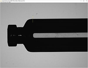
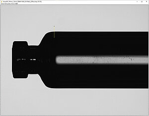
The silhouette illumination described above is the primary application for edge measurement. However, these illumination systems are also ideally suited to inspecting transparent objects such as glass or diamonds. Streaks, scratches or inclusions become visible in the parallel light. Whenever light encounters a defect, it is deflected out of the beam path and is therefore missing from the evaluation. The affected area appears dark. This method is highly sensitive, as demonstrated by the remaining illuminated strip inside the glass ampoule in the example. For this purpose, the light can be introduced via a suitable beam splitter.
High-power versions of our TZBs have been specifically developed for inspection applications. The aim is to direct as much parallel light as possible onto the sample. These are available as 24 V versions or Smart Light versions. The latter also enables the illumination to be pulsed in conjunction with our controller.
Dimensional measurement can therefore be carried out particularly effectively on glossy or transparent objects in conjunction with telecentric illumination. Possible applications include wires, metal pins, glass rods, glass ampoules, threads and liquid jets. Bridges and grooves on reflective surfaces, as well as coating thicknesses in semiconductor manufacturing, can also be measured. A special application is Direction-Coded Deflectometry (RCD), which enables three-dimensional measurement of reflective surfaces.
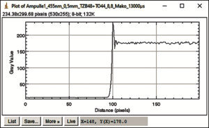
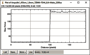
The following example demonstrates how a larger aperture diameter largely eliminates disturbing coherence effects during edge detection. The setup used a blue TZB48 in combination with the TO44/8.8-110-V-BW and a Mako camera from AVT with a pixel size of 2.2 µm.
In the first case, measurements were taken with an aperture diameter of 0.5 mm, resulting in a divergence of 0.14° (Figure 4). Pronounced overshoot effects are still visible here. In the second case, the aperture was increased to 1.6 mm (Figure 5). This results in a divergence of approximately 0.46°. A continuous edge profile without disturbing ringing can be observed.
The following table provides an overview of the optimum aperture diameters incorporated into Vision & Control telecentric illumination systems, which are required to suppress coherence effects.
Aperture diameter for optimum divergence
TZB | Focal length | Half divergence angle | Aperture diameter |
10 | 35 | 0.46° | 0.6 mm |
28 | 75 | 0.46° | 1.2 mm |
38 | 80 | 0.46° | 1.3 mm |
48 | 100 | 0.46° | 1.6 mm |
72 | 150 | 0.46° | 2.4 mm |
94 | 245 | 0.46° | 3.9 mm |
130 | 290 | 0.46° | 4.7 mm |
Conclusion
Telecentric illumination systems from Vision & Control are ideally suited to measurement and inspection applications, particularly for transparent objects such as glass or diamonds.