The first step in planning a machine vision application is to select the correct lighting for the objects to be evaluated. Whatever is lost here due to inadequate lighting cannot be reconstructed later on in the image processing sequence. The choice of lighting influences measurement accuracy and the visibility of the relevant object attributes.
Telecentric lenses in and of themselves offer many advantages which make high-precision measurement and the visualization of specific object attributes possible. However it takes the right lighting to get the most out of these lenses. In principle, objects can be inspected and measured using any of the familiar machine vision lighting techniques. This means that incident light, transmitted light, bright field and dark field are all viable options. The choice of lighting depends on the angle of incidence which significantly enhances the visibility of the object attributes and also on whether the angular range should be large or small.
Diffuse lighting produces a wide angular range. It is used for example when minute structural details are of interest such as tracks and device ID numbers on PCBs. In this case, what is needed is an image with good contrast rendition of the spatial frequencies which carry the information. An image of the object is produced on the sensor using conventional imaging with a telecentric lens. The resolution depends on the numerical aperture of the lens. The principle characteristic curve for this technique is the modulation transfer function (MTF) which describes the contrast ratio for the various spatial frequencies.
If the objective is to emphasize edges and surface structures, directed lighting must be used. Telecentric lighting is a highly directed type of lighting. Ideally, it only emits collimated light, in other words light with an inclination angle of 0° to the optical axis. In reality, light is emitted over a very small angular range. The relevant image information is produced through shadow casting by the object or individual object structures. The high contrast makes it possible to very accurately determine the location of the edge. This is useful for imaging the object shape or geometry, for example to verify that parts conform to dimensional specifications.
Before looking at the specific applications, the following section explains how directed rays can be produced and how this type of lighting can be used to the greatest effect in conjunction with the lens.
Operating principle
The basic design of a telecentric lighting system is shown in the left portion of the complete optical system in Fig 1. The light source is located at the focal point F of an optical system. The rays come from infinity, creating a parallel beam path. However, light with ideal parallelism can only be produced with a point light source. In reality, the light sources always have a certain spatial extent.

Fig. 1: Basic principle showing how telecentric lighting and a telecentric lens are used together.
LEDs around a tenth of a millimeter in size are typically used for this purpose. The dimensions of the light source and the focal length of the optics influence ray parallelism. Deviation from parallelism decreases as focal length increases, but the length of the telecentric lighting also increases. As a result in contrast to a diffuse light source, the length of telecentric lighting is in the 100 – 200 mm range. Divergence angles ((jlighting in Fig. 1) are in the 0.5° - 1° range. Due to the parallelism of the ray paths, the diameter of the lighting optics must be at least as large as the object under evaluation.

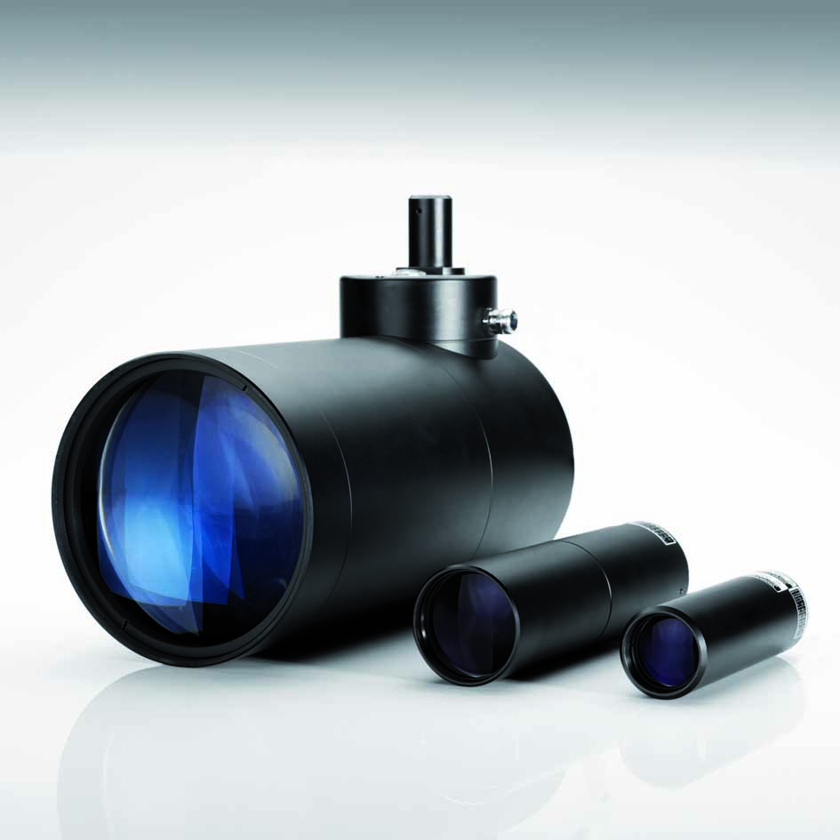
Fig. 2: Different telecentric lighting versions (Source: Vision & Control)
The basic principle behind telecentric lighting makes it clear that this type of lighting can only be used in conjunction with telecentric lenses. It is the only technique which enables the beams of light for the outer field positions to be imaged by the lens. If the angular aperture of the telecentric lens harmonizes with the illumination aperture of the light source (i.e. if it is not larger), only the light from the object is included in the image and the object measurement. Stray light can be excluded. The light source and the lens must be well aligned with each other, and lens mounts are available for this purpose.
Telecentric lighting produces a uniform illumination field. A caustic (an area with minimum light diameter) is formed at the focal point of the illumination optics. Ideally, that is where the object should be placed. However due to the extremely low divergence of the beams, the object can actually be placed at some arbitrary position in front of the light source. Experience shows that this does not impair the measurement or inspection result.
In contrast to the human eye, the camera does not see the light source due to the telecentric perspective when the object is imaged. Fig. 1 shows that the image of the light source is produced in the focal plane of the TZO. The image of the object, however, is produced in a different plane which is further away from the lens. In contrast, the human eye sees objects with an entocentric perspective. The entrance pupil is located close to the imaging lens. If the eye focuses on infinity, the image of the light source for the telecentric lighting appears on the retina.
Due to the low illumination aperture which is captured by the lens, the image has an extremely high depth of field. The objects can be positioned within a very large area along the optical axis around the working distance.
Because the light is already supplied in the relevant direction, exposure times can be relatively short with this lighting. Compared to imaging with diffuse light, exposure times can be shorter by a factor of 10 – 20 when telecentric lighting is used.
The differences in exposure time for telecentric and diffuse light are particularly large for objects which have significant depth. The lens aperture must be reduced to produce the necessary depth of field. With diffuse light however, this means that light supplied in many directions is blocked out and cannot be used to create the image. This is compensated for by increasing the exposure time.
In contrast to lasers which also have a definite directional characteristic, no spurious speckles appear with this lighting.
Applications
Telecentric lighting is typically used to measure the dimensions of shiny or transparent objects such as wire, metal bolts, glass ampoules, thread and even jets of liquid. It can also make inclusions and voids in glass and other transparent materials visible. This type of lighting is also used in deflectometry, a technique for measuring deviations from the ideal characteristics of specular surfaces. When light is deflected from the ideal beam path, the affected area appears to be dark and this absence of light is detected during image evaluation. This effect is used to detect defects. Under incident light, ridges and indentations as well as paint thickness can be detected on reflecting surfaces. The technique is now widely used in semiconductor production.
The following examples show how telecentric lighting is used to measure shiny metal parts.

Fig. 3: Metal bolt in diffuse (left) and telecentric (right) lighting. To obtain a high-contract image of the edges and thus accurately determine the diameter, it is necessary to use telecentric lighting.
Accurate contour detection is a general problem because under diffuse light unwanted reflections appear in the image which can lead to an extreme reduction in the contrast of the edge. This makes it difficult or impossible to detect the exact location of the edge, for example by using a mean grayscale level. Fig. 3 shows images of a bolt under diffuse (left) and telecentric (right) lighting. The poor contrast at the edge under diffuse lighting makes it impossible to detect the correct location of the edge in order to determine the diameter. The sharp image of the edge with telecentric lighting makes it possible to measure the object dimensions. The following images of a screw (Fig. 4) and a spring (Fig. 5) show similar effects. Reflections at the sides of the screw make it impossible to accurately detect the location of the edges under diffuse light. To reliably detect the screw contours and derive specific parameters such as thread pitch, it is necessary to use telecentric lighting.

Fig. 4: Screw in diffuse (left) and telecentric (right) lighting.

Fig. 5: Spring in diffuse (left) and telecentric (right) lighting.
The following images show measurement and inspection applications for transparent materials. In Fig. 6, a glass rod was illuminated with diffuse (left) and telecentric (right) lighting. The exact location of the edge cannot be precisely determined under diffuse light because the edge contour is not clearly defined. Clear object contours can be seen under telecentric lighting, making measurements of the object possible. Because telecentric lighting is collimated, only the light beams which strike the surface at a perpendicular angle, producing the bright line in the middle and the peripheral light outside of the object contours, appear in the image. The same effect can be seen with the glass vials which are shown in Fig. 7. Due to propagation of light inside the bottle, the luminous stripe in the middle appears larger than on the solid glass rod. Bild 8 shows a glass plate imaged in diffuse (left) and telecentric (right) transmitted light. Only a scratch can be seen in the left image. Scratches, dirt, voids and streaking appear in the image on the right.

Fig. 6: Glass rod in diffuse (left) and telecentric (right) lighting.

Fig. 7: Glass vials in diffuse (left) and telecentric (right) lighting.

Fig. 8: Glass plate with defects (scratched, dirty, chipped) in diffuse (left) and telecentric (right) lighting.
In summary, telecentric lighting is used for detecting the contours of shiny and transparent items and flowing liquid. High-contrast edges can be seen in the images as a result of shadow casting. The edges can be accurately detected and measured with high precision. Surface structures on transparent objects viewed in transmitted light as well as geometric deviations and coating layer variance on reflecting objects viewed in incident light can be made visible.
appeared in MaschinenMarkt 13/2014